In this research attention will be on different techniques and methods for joint angle sensors. Emphasis will be on parameters and signal generation.
Technique 1: Angular position sensors in the joint
The authors in [4] were interested in the concept of developing an implantable joint angle transducer (IJAT) based on Hall effect sensors was proposed by [4] to be used in neuroprostheses. Hall Effect sensor is a device that converts the energy stored in a magnetic field to an electrical signal.
The Hall effect is an ideal sensing technology and the working principle of the Hall effect sensor is very simple. The Hall element is constructed from a thin sheet of conductive material with output connections perpendicular to the direction of current flow. When subjected to a magnetic field, it responds with an output voltage proportional to the magnetic field strength. The voltage output is very small (millivolt) and requires additional electronics to achieve useful voltage levels. When the Hall element is combined with the associated electronics, it forms a Hall effect sensor. Although the Hall effect sensor is a magnetic field sensor, it can be used as the principle component in many other types of sensing devices (current, temperature, pressure, position, etc.).
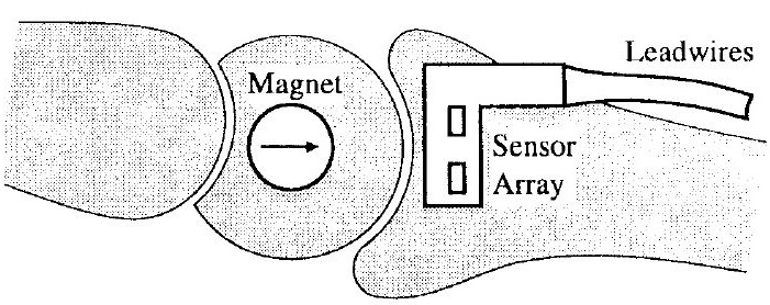
In the figure 3.1, Hall Effect sensor and magnet are used to measure joint angle. Hall sensors are mounted on a stator, positioned in front of the rotor. Behind the stator, a permanent magnet has the role of generating a magnetic field. By moving the rotor, a change in the magnetic field is produced which is picked up using the Hall sensors and further processed by electronic circuitry.

Figure 3.1: Schematic diagram of implantable joint angle transducer showing a permanent magnet implanted in one bone, and a sensor array implanted in the opposing bone, with lead wires running proximally. The permanent magnet is at center of rotation [4].
Technique 2: Flex/bend sensors following the curvature of the joint or mounted on the joint
Soft robotics is a new paradigm in robotics, which aims to mimic the inherent compliance of natural soft-bodied systems (for example: natural muscle). Creating soft-bodied robots requires a new class of active soft materials that maintain the functionality of traditional components (sensors, actuators and electronics). Soft materials can be made active in that they can greatly change shape, volume or property in response to diverse stimuli, requiring innovations in applied mechanics, materials, and novel fabrication methods [5]. In the present article curvature sensor were used as a joint angle proprioception.
Curvature and joint angle sensors allow real-time kinematic feedback in robotic manipulation, which is necessary for a system to react intelligently to its environment [9]. A thin metal lm strain gage, which operates with 100 - 750 Ohm resistance and is accurate to within 10 degrees [6]. The metal lmit conducts electricity but also resists its flow somewhat. When the sheet is bent one way it stretches the foil slightly, making it longer and thinner. This raises its resistance, since the electricity has further to go and a more path to follow. On the other hand, when the sheet is bent in the other direction it compresses the foil, making it shorter and wider and lowering the resistance. Because the lm strip is so long, even slight strains will cause fairly big changes in the resistance, which will be picked up by the Wheatstone bridge.

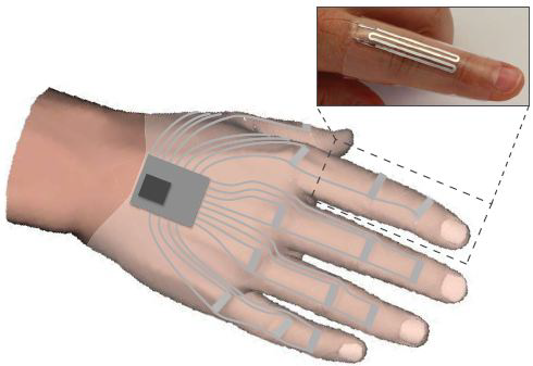
Figure 3.2: An illustration measurement of human hand covered with curvature sensor at every joint [5].
In figure 3.2 a sensor (stretch, pressure and curvature) was used to detect bending and joint position and that are composed of all compliant elastomer and liquid materials. The knuckle applied pressure to the sensor embedded microchannel during bending and increasing the measured change in resistance. The sensors are put around a finger joint with the embedded sensing element, which are positioned above the middle knuckle. Bending the finger will cause the knuckle to stretch the elastomer and put a pressure on the sensing element. The combination of stretching, pressure, and curvature force a change DR in the electrical resistance of the sensor. Finger bending is measured when the relative change in resistance r = DR/R0 exceeds a critical threshold. The joint angle may also be estimated from the change in resistance, although this requires the sensor to be calibrate. [5].
Other approaches that provide a rough estimate of the bending angle use piezoresistive strain gauge arrays. They are used in interaction gloves and have different lengths, according to the number of the elements arranged in series in the array. These elements are often carbon patches and they change the resistance if bend. The principle of operation is depicted in figure 3.3(a) where the bend direction and the curvature radius have a direct influence on the resistance value. Figure 3.3(b) depicts a typical bend sensor manufactured by Spectra Symbol.

Figure 3.3: Angular bend sensors (a) principle of operation (b) typical sensor, manufactured by Spectra Symbol.
Technique 3: Optoelectronic joint angle
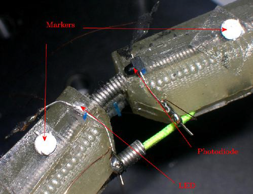
Cavallo and his team [10] created a sensor at the university of Bologna Italy, which is based on a couplet to LED/photodiode, mounted to two contiguous phalanges hand finger. When the joint between the considered phalanges flexes, the photocurrent measured by the photo detector changes with the angular displacement. When a current drives the LED, it emits light, which is coupled to the photodetector through the dielectric. The photodetector generates a current that is proportional to the coupled light.
An LED and a photodetector are situated respectively on the first and second phalanx interconnected by the joint, facing each other with mechanical axes overlapping. In this situation a certain amount of light emitted by the LED reaches the photo detector and it is proportionally shifted into an electrical current, I0 [10].
In figure 3.4 is illustrated the mounted sensor. It has been calibrated using a Vicon 460 optical motion capture system. A reflective marker has been attached to each phalanx contiguous to the joint with the mounted devices. A couple of experiments has been made with the motion capture system in order to reconstruct the 3D space position of each marker when the joint is flexed [10].

Figure 3.4: Detail of the sensor mounting [10].
Technique 4: Accelerometer and Gyroscope for joint angle measurement of the leg sections in respect to each other
Bengt Oelemann with his Ph.D. student Peng Cheng [11] analysed in the laboratory of Sweden University, a rigid-body joint angle measurement based on microelectromechanical system (MEMS) biaxial accelerometer and uniaxial gyroscope by using four different sensor combination methods. These methods are: Magnetic and Optical encoder. Magnetic encoder which incorporate with a multipole magnet and a Hall effect sensor. Optical encoder also incorporate with a disk which is very precise for window edge cut and a photodetector which is discussed also in the earlier section.
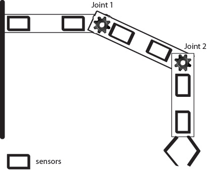
In figure 3.5 the arm of the robot with two joint and three links can be seen. A biaxial accelerometer and yaw rate gyroscope are vertically attached to each pickup point. There are two pickup points on each link [11]. The sensors are mounted on the joint are: KXR94–2050 from Kionix [12], for the MEMS
accelerometer, which is an analog triaxial accelerometer and ADXRS612 from analog devices [13], for the MEMS gyroscope. All signal channels from both sensors have been buffered and converted analog-to-dital signal.

Figure 3.5: Robot arm and the sensors.
Another proposed sensor is a vibratory micro-gyroscope [14]. This silicon micromachined vibratory microgyroscope depends on the Coriolis force to induce energy transfer between oscillating modes in order to detect rotation. It has large dynamic range and a low power consumption, as well as long
lifetime. Inductive position sensors are also pointed out for measuring angular displacements [14]. Cheaper alternatives for measuring the joint angles could rely on analog potentiometers based on resistive plates. However their lifetime and reliability are a limiting factor.
Bibliography
[4] M.W. Johnson, P.H. Peckham, N. Bhadra, K.L. Kilgore, M.M.
Gazdik, M.W. Keith, and P. Strojnik. Implantable transducer for two-degree of freedom joint angle sensing. Rehabilitation Engineering, IEEE Transactions on, 7(3):349 {359, sep 1999.
[5] Rebecca K. Kramer, Carmel Majidi, Ranjana Sahai and Robert J. Wood. Soft Curvature Sensors for Joint Angle Proprioception, IEEE International Conference on Intelligent Robots and Systems, 1919 { 1926, Sep 2011.
[6] E. Jesperson and M. Neuman, \A thin film strain gauge angular displacement sensor for measuring finger joint angles,” in Engineering in Medicine and Biology Society, 1988. Proceedings of
the Annual International Conference of the IEEE. IEEE, 2006, pp. 807{vol.
[7] G. Brasseur, \A capacitive finger-type angular-position and angularspeed sensor,” in Instrumentation and Measurement Technology Conference, 1998. IMTC/98. Conference Proceedings.
IEEE, vol. 2. IEEE, 1998, pp. 967{972.
[8] Y. Liu, L. Zhang, J. Williams, and I. Bennion, “Long-period fibre grating bend sensor based on measurement of resonance mode splitting,” in Lasers and Electro-Optics, 2000.(CLEO 2000). Conference on. IEEE, 2000, pp. 306{307.
[9] B. Gwandu, X. Shu, Y. Liu, W. Zhang, L. Zhang, and I. Bennion, “Simultaneous measurement of strain and curvature using superstructure fibre Bragg gratings,” Sensors and Actuators A: Physical, vol. 96, no. 2–3, pp. 133{139, 2002.
[10] A. Cavallo, G. De Maria, C. Natale, S. Pirozzi, “Optoelectronic joint angular sensor for robotic fingers,” Sensors and Actuators A” Physical, vol. 152, pp. 203–210, 2009.
[11] Peng Cheng, Student Member, IEEE, and Bengt Oelmann, vol. 59, pp. 404–414, 2010.
[12] KXR94–2050, Ithaca, NY: Kionix, 2008. www.kionix.com
[13] ADXRS612, Norwood, MA: Analog Devices, 2008. www.analog.com
[14] P. Dario, C. Laschi, S. Micera, F. Vecchi, M. Zecca, A. Menciassi, B. Mazzolai, and M. C. Carrozza. Sensors and Sensing in Biology and Engineering, chapter Biologically-inspired microfabricated force and position mechano-sensors, pages 109{125. Springer-Verlag, Berlin, 2003.